Evaluating the Physical Disparity in Legacy Cable Plants
The migration of physical security infrastructure from isolated, on-premises local area networks to integrated, cloud-native environments exposes severe operational limitations within legacy low-voltage cable plants. Commercial surveillance and access control systems relied for decades on highly fragmented physical architectures. Analog video was transmitted over thick RG59 coaxial cabling, proximity card access data traveled via multi-conductor untwisted 22 AWG cables, and early-generation IP cameras utilized rudimentary Category 5e (Cat5e) horizontal runs supplying minimal Power over Ethernet (PoE). Modern facility security demands a unified, highly resilient physical layer capable of sustaining high-bandwidth, continuous data streams while simultaneously delivering substantial direct current (DC) power to sophisticated, multi-sensor edge devices.
Licensed security contractors operating within the jurisdiction of the Illinois Private Alarm Contractor Act of 2004 (225 ILCS 447) must evaluate the physical gap between existing cable infrastructures and current operational requirements through rigorous analysis of bandwidth ceilings, thermal dissipation physics, and network load balancing. The legal scope of work dictates that any integration of surveillance, access control, and life safety systems must adhere strictly to current electrical and building codes. Older Cat5e infrastructure, engineered with thin 24 AWG conductors, is restricted to a frequency bandwidth ceiling of 100 MHz. This physical limitation reliably supports 1 Gbps transmission speeds over a maximum channel length of 100 meters. This bandwidth was technically sufficient for legacy single-sensor 1080p cameras, yet it operates as a severe bottleneck when deploying the current generation of multi-sensor panoramic IP cameras or aggregated, multi-door access control cloud controllers. Category 6A (Cat6a) cabling operates at a 500 MHz frequency, delivering 10 Gbps throughput over the identical 100-meter channel. This expanded frequency provides the necessary data headroom for continuous 4K video streams and concurrent analytical metadata transmission.
Evaluating the evolution of Power over Ethernet delivery reveals the most pronounced disparity between legacy and modern infrastructure. The progression of PoE standards from the original IEEE 802.3af (15.4W) to 802.3at (PoE+ 30W), and ultimately to the current IEEE 802.3bt standard (PoE++ Type 3 at 60W and Type 4 at up to 90W), places unprecedented electrical strain on horizontal structured cabling. High-power PoE++ forces power across all four twisted pairs simultaneously to achieve a 90W output at the Power Sourcing Equipment (PSE). This guarantees a minimum delivery of 71.3W to the Powered Device (PD) after accounting for natural voltage drop across the copper run. Pushing nearly 1 ampere of current (up to 960 mA) through tightly bundled copper conductors generates significant I^2R resistive heating. The basic laws of physics dictate that the higher the power pushed through narrow copper gauges, the greater the heat generated.
Thermal Dissipation Physics and Insertion Loss
Thermal rise directly and negatively impacts data transmission integrity. Cable temperatures elevate rapidly within tightly packed conduit bundles, causing the copper’s DC resistance to increase proportionally. This physical reaction exacerbates voltage drop and significantly increases insertion loss, forcing the digital signal to attenuate before reaching its intended destination. Field engineers utilizing advanced diagnostic equipment, such as Fluke handheld analyzers, routinely observe this specific attenuation when evaluating overheated cable plants. Left unchecked, this physical degradation ultimately leads to severe bit errors, packet retransmissions, unexpected edge device reboots, and the premature physical melting of the outer cable jackets.
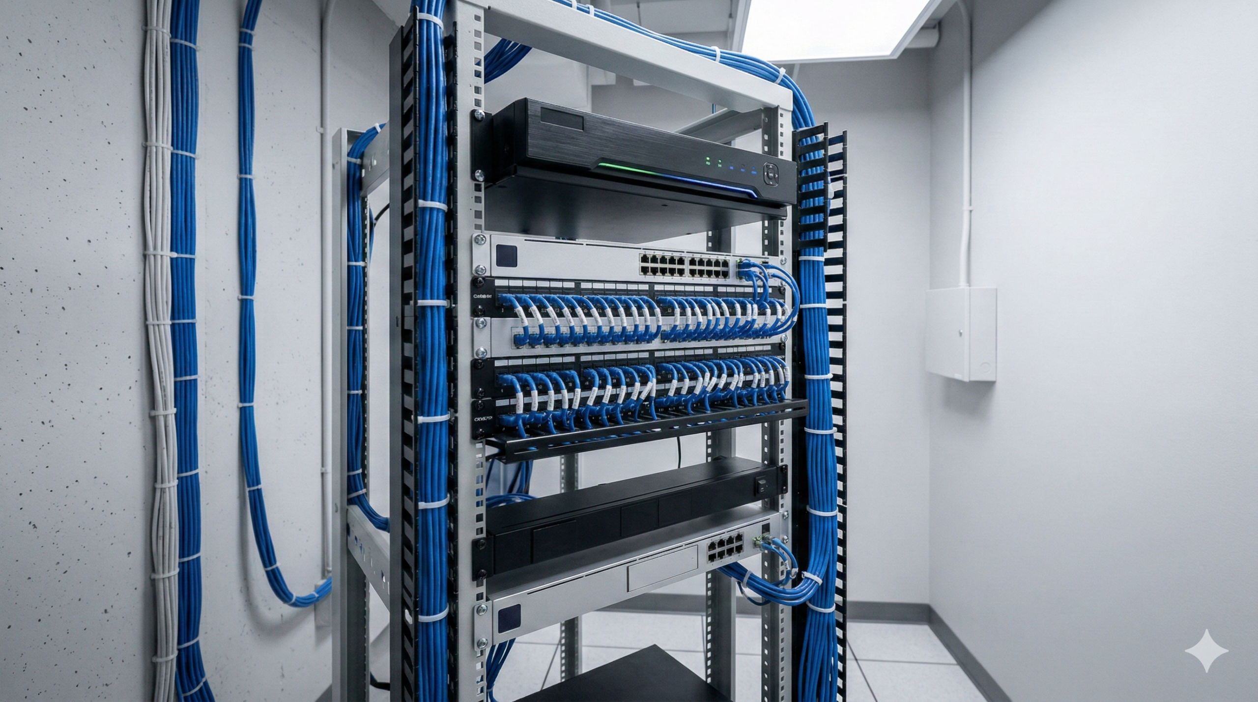
Boots-on-the-ground technicians frequently encounter horrific wiring jobs left by untrained contractors who ignore these thermal realities. Telecommunication closets filled with rats’ nests of unlabeled wires, excessive bend radius violations, and overloaded J-hooks directly degrade system performance. When a bundle of legacy Cat5e cables is carrying maximum PoE++ loads, the cables trapped in the dead center of the bundle have absolutely no thermal escape path. The heat builds exponentially. Identifying these faults requires specialized testing hardware. Field personnel rely heavily on devices like the TREND Networks PoE Pro tester to determine whether sufficient power is actually reaching the endpoint. This compact tester identifies the Class of the PoE source (0-8), the maximum watts available, the voltage, the standard type (af/at/bt), and verifies 2/4 pair operation. Verifying these metrics locally prevents technicians from wasting hours attempting to diagnose a suspected faulty IP camera when the root cause is actually severe voltage drop caused by an overheated, undersized copper run.
NEC 725.144 Ampacity Compliance and Bundle Limitations
Mitigating fire and operational hazards requires strict adherence to the National Electrical Code (NEC) Article 725, which governs the installation of Class 2 and Class 3 power-limited circuits. The introduction of NEC Article 725.144 established mandatory ampacity tables dictating the maximum permitted current per conductor based on the American Wire Gauge (AWG) size, the cable’s mechanical temperature rating (typically 60°C, 75°C, or 90°C), and the total number of cables contained within a physical bundle. The 2020 edition of the NFPA 70 NEC refined Table 725.144 further. This revision utilized true rounding mathematics to slightly increase the tabulated conductor ampacity ratings, providing integrators with more precise thresholds for high-density remote powering deployments.
Adherence to these thermal limits remains an absolute mandate for licensed security contractors executing installations in commercial facilities. Installing conventional 24 AWG Cat5e in massive conduit bundles to supply 90W PoE++ devices rapidly exceeds the cable’s maximum temperature rating, risking physical insulation melting and strict non-compliance with commercial fire codes. Adjusting Table 725.144 calculations to account for a standard 45°C ambient environment with a 15°C allowable rise demonstrates the stark difference in cable capacities. A Cat6a cable constructed with 23 AWG conductors and a 75°C mechanical rating can safely transmit 450mA per conductor within massive bundles of up to 192 cables. A standard Cat5e 24 AWG 75°C cable restricts the maximum compliant bundle size to exactly 91 cables to carry a similar 460mA load.
The immense scale of power passing through these architectural choke points is staggering. A fully saturated 192-cable bundle carrying 433mA per conductor from a 52V source delivers 17.3 kilowatts of aggregate power directly into the ceiling space. A 91-cable bundle under the same load carries 8.2 kilowatts. Pushing this magnitude of raw electrical energy through low-voltage pathways requires absolute engineering discipline.
The implementation of 23 AWG Cat6a cable inherently solves many of these thermal congestion issues. Engineered with a thicker copper mass and internal cross-web splines, Cat6a offers vastly superior heat dissipation compared to legacy 24 AWG wiring. This heavier gauge effectively reduces core temperature rise and allows for maximum compliant bundle sizes without exceeding IEEE standards or triggering NEC ampacity violations. Shielded variants, including F/UTP or S/FTP constructions, offer even greater noise immunity and heat dissipation capabilities when deploying dense server farm links or heavy industrial manufacturing surveillance grids.
Mathematical Efficiency in Video Compression Codecs
Calculating and mitigating the logical network load generated by continuous high-resolution video streams requires a deep understanding of mathematical compression algorithms. The mathematical efficiency of the specific video compression codec serves as a critical variable in physical infrastructure planning. The legacy H.264 (Advanced Video Coding) standard processes video frames using rigid 16×16 pixel macroblocks. Transmitting a 4K resolution (3840 x 2160 pixels) stream at 30 frames per second using an H.264 codec typically demands a continuous network bitrate of 18 to 20 Mbps to maintain acceptable visual fidelity. Multiplying this heavy data load across dozens of surveillance nodes in a commercial facility rapidly overwhelms legacy gigabit switch backplanes and saturates edge uplinks.
Transitioning to H.265 (High Efficiency Video Coding) fundamentally alters this network load calculus. H.265 replaces static macroblocks with highly variable Coding Tree Units (CTUs). These mathematical constructs process variable block sizes ranging from 4×4 up to 64×64 pixels based entirely on contextual frame data. Heavy optimization of motion compensation and spatial prediction algorithms allows H.265 to achieve an approximate 50% increase in compression efficiency over legacy H.264 architectures. An identical 4K stream encoded in H.265 requires only 7 to 10 Mbps of network bandwidth to deliver indistinguishable image quality. This drastically reduces the data transmission load on the physical cable plant and yields massive storage retention savings at the centralized recording appliance.
Recording appliances within the industry are explicitly categorized by their ingestion architecture. A Network Video Recorder (NVR) serves as the central hub, utilizing a built-in hard drive to record and store packetized digital video from IP cameras over a network. A Digital Video Recorder (DVR) remains a legacy device that captures raw analog signals from coaxial cameras and handles the analog-to-digital conversion internally. The eXtended Video Recorder (XVR) acts as a hybrid bridge technology, offering extended compatibility to ingest both traditional analog formats (like HD-CVI or HD-TVI) and modern IP streams simultaneously. For modern cloud-native environments, pure NVRs or direct-to-cloud architectures bypass the XVR requirement entirely. Shifting the H.265 processing burden to the edge device requires modern IP cameras to possess advanced onboard silicon processors capable of executing these complex compression algorithms in real-time before pushing the data down the wire.
| Codec Specification | H.264 (Advanced Video Coding) | H.265 (High Efficiency Video Coding) |
| Processing Architecture | Fixed 16×16 Pixel Macroblocks | Variable 4×4 to 64×64 Pixel Coding Tree Units (CTUs) |
| Average Bitrate (4K @ 30fps) | 18.0 – 20.0 Mbps | 7.0 – 10.0 Mbps |
| Bandwidth Efficiency | Baseline standard | Yields ~50% reduction in network bandwidth load |
| Hardware Processing Load | Low (Compatible with legacy encoders) | High (Requires advanced silicon for real-time encoding) |
| Storage Impact (Archival) | Baseline capacity | Yields massive recorded footage retention per Terabyte |
Edge Analytics and the Viterbi Algorithm
Advanced video analytics rely heavily on mathematical modeling to establish fluid, highly accurate object tracking trajectories. Modern AI-enabled edge cameras execute localized machine learning models to classify objects, distinguish human forms from vehicular traffic, analyze loitering patterns, and filter out environmental noise. Many of these tracking capabilities leverage the Viterbi algorithm. This algorithm is a sophisticated dynamic programming method utilized to find the most probable sequence of hidden states within a Hidden Markov Model (HMM).
The Viterbi algorithm processes sequential data to determine underlying hidden events based on observed surface-level events. A security camera tracking a human subject moving through a crowded retail environment or passing behind physical occlusions, such as support pillars or store displays, utilizes this mathematical framework. The camera’s internal processor evaluates the maximum likelihood probability of the object’s spatial location across successive video frames. The Viterbi path effectively decodes the trajectory, allowing the camera’s tracking unit to maintain a continuous lock on the target even when direct visual line-of-sight is temporarily broken. This heavily computational process far exceeds the unreliable capability of basic pixel-change motion detection, which triggers false alarms on moving shadows, swaying trees, or precipitation.
Executing computational tasks like recursive Viterbi path decoding, complex AI object classification, and driving motorized optical zooms requires massive amounts of continuous electrical power. Edge analytics models push the absolute limits of the IEEE 802.3bt Type 4 (90W) PoE standard. Infrastructure engineers must precisely match the network switch’s total overall PoE power budget to the aggregate maximum draw of the powered devices. Connecting multiple high-draw Pan/Tilt/Zoom (PTZ) units or edge-computing analytics cameras to an under-provisioned switch triggers an immediate hardware self-preservation mechanism known as port shedding. The network switch will forcibly disable power to lower-priority ports to protect its internal power supply from catastrophic thermal failure, instantly blinding sections of the surveillance grid.
Transitioning to Decentralized Access Control Topologies
Rapid proliferation of multi-sensor panoramic IP cameras dictates a fundamental redesign of the access layer. Commercial facilities no longer rely on dense arrays of singular, narrow field-of-view lenses. A single deployment location on a building exterior frequently houses a sophisticated quad-sensor device featuring motorized Pan/Tilt/Rotate/Zoom (PTRZ) mechanics paired with an integrated high-speed PTZ unit. This entire hardware array draws power and data from a single network cable home-run. Delivering up to 90W of continuous power to drive internal lens motors, wide-angle infrared (IR) illuminators extending beyond 200 meters, and integrated thermal management heaters requires an infrastructure explicitly designed for maximum power delivery without voltage degradation. Voltage dropping below the specific operating threshold of the powered device due to elevated cable resistance over long horizontal runs causes the camera to fail initialization or experience spontaneous reboots during high-draw events. Strategies to address this voltage drop include minimizing physical cable lengths, enforcing the deployment of heavy-gauge Cat6a copper, and selecting specialized PoE injection equipment.
Architectural models for commercial access control are pivoting sharply from localized, serial-based topologies to highly decentralized, cloud-native deployments. Modern electronic strikes, high-holding-force magnetic locks, and multi-factor biometric terminals rely on intelligent edge controllers that communicate directly with remote cloud servers via standard IP protocols over Ethernet networks. Physical security hardware must be treated with the exact same network infrastructure rigor as enterprise IT equipment. Legacy 22 AWG multi-conductor wiring, utilized for decades to transmit unencrypted pulse-based data from door readers to centralized wall-mounted panels, proves fundamentally incompatible with the high-bandwidth and continuous power requirements of cloud-connected biometric authentication terminals.
Legacy Vulnerabilities: The Wiegand Protocol
Migrating away from the Wiegand interface constitutes a critical security mandate for modern facilities. Developed in the 1980s, the legacy Wiegand protocol utilizes a simplistic, unidirectional, multi-wire topology. A standard proximity card reader transmits unencrypted D0 and D1 electrical data pulses directly to an access controller. These pulses represent bits of data sent across two wires based entirely on voltage levels. Wiegand lacks native encryption completely. Physical access to the exterior reader wiring allows malicious actors to deploy cheap, easily obtainable skimming hardware. Bad actors routinely purchase devices like the ESP Key for less than $100. Attackers simply remove a wall-mounted card reader and splice this miniature BLE-enabled shunt directly onto the exposed legacy wiring to sniff the data traveling across the copper. This plain-text data interception allows attackers to harvest and clone proximity card access credentials instantaneously.
Unidirectional communication represents another severe architectural flaw. The core access controller cannot query the reader for physical tamper alerts, firmware versioning, or general operational health status. This creates critical security blind spots and prolonged diagnostic times during device failures. Field technicians are forced to manually inspect reader hardware with multimeters to diagnose simple communication faults, escalating operational maintenance costs and network downtime.
Implementing OSDP Secure Channel Cryptography
The Security Industry Association (SIA) standardized the Open Supervised Device Protocol (OSDP) to neutralize these exact physical vulnerabilities. OSDP is a highly secure, bidirectional communication standard operating over an RS-485 serial bus. This protocol utilizes only four physical conductors: Power, Ground, Data A (TX/RX+), and Data B (TX/RX-). The defining feature for modern commercial deployments is the OSDP Secure Channel requirement. This feature strictly enforces AES-128 encryption across the RS-485 data line.
Initiating an OSDP Secure Channel connection forces the access control panel and the peripheral device to execute a highly complex cryptographic challenge-response sequence. The devices mutually authenticate their respective identities before any credential data is permitted to transmit. This encryption framework neutralizes man-in-the-middle line taps and entirely prevents credential replay vectors. Even if an attacker physically splices into the RS-485 line, the captured data stream consists of mathematically unreadable ciphertext.
| Protocol Specification | Legacy Wiegand Protocol | OSDP (Open Supervised Device Protocol) |
| Communication Direction | Unidirectional (Reader ⇉ Controller) | Bidirectional (Reader ⇆ Controller) |
| Physical Wiring Topology | 6+ conductors, point-to-point only | 4 conductors (RS-485), supports multi-drop |
| Data Encryption Standard | None (Credentials transmitted in plain text) | AES-128 (via OSDP Secure Channel) |
| Maximum Cable Distance | ~150 meters (500 feet) | ~1200 meters (4,000 feet) |
| Device Supervision | Non-existent | Continuous polling, real-time tamper alerts |
Bidirectional polling natively facilitates the integration of sophisticated edge hardware. Advanced multi-modal biometric terminals and readers equipped with Bluetooth Low Energy (BLE) and Near Field Communication (NFC) chipsets rely heavily on this bidirectional pipeline. The host controller transmits complex data sets back to the reader, enabling custom LCD text prompts, personalized access granted messages, and remote over-the-air (OTA) firmware updates. The RS-485 standard allows OSDP to support a multi-drop daisy-chain topology. Multiple card readers can be wired in series along a single continuous cable run. This significantly reduces the labor and copper costs associated with pulling individual home-run wires back to the telecommunications room for every peripheral device.
Municipal Code Compliance and Multi-Tenant Bottlenecks
Aggregating distinct security networks in multi-tenant commercial facilities poses severe physical and logical bottleneck risks. Industrial and retail corridors feature sprawling commercial footprints where individual tenants frequently share pathway conduits. Upgrading individual tenant security hardware severely congests these shared conduits. Congestion increases the localized ambient temperature within the pipe, reducing the effective ampacity of the installed cables per NEC 725.144 derating guidelines. Designing multi-tenant architectures requires precise calculation of the total PoE power budget demanded by the aggregated edge endpoints and the cumulative network bandwidth routed back to the core switching infrastructure. Implementing Cat6a horizontal wiring alongside high-capacity fiber optic backbones circumvents these physical layer constraints and prevents individual tenant security operations from suffering latency degradation due to shared infrastructure saturation.
System designs must strictly comply with heavy regulatory oversight from local municipalities. The Village of Wheeling Community Development Department and Fire Prevention Bureau actively enforce these standards. Effective May 1, 2025, the Village of Wheeling formally adopts the 2021 International Building Code (IBC) and 2021 International Fire Code (IFC), along with specific local amendments codified in Title 14 (Fire) and Title 15 (Buildings and Construction) of the Municipal Code. Alterations to commercial electrical and fire alarm systems require rigorous plan reviews and mandatory low-voltage electrical permits.
Commercial fire protection requirements strictly dictate access control integration. Title 14 amendments mandate that commercial fire sprinkler systems, isolation OS&Y valves, fire pumps, and flow switches must be monitored 24 hours a day by an approved alarm monitoring service. Any physical access control system deploying electronic magnetic locks or electrified strike hardware on egress pathways must directly interface with the building’s Fire Alarm Control Panel (FACP). Upon the initiation of a fire alarm condition, the FACP must trigger an immediate relay to drop DC power to all perimeter and internal magnetic locks, ensuring unimpeded life-safety egress for building occupants. The Village of Wheeling formally inspects all commercial occupancies for compliance approximately once every three years, and requires an annual alarm permit for active systems. Unlicensed or non-compliant installations risk immediate operational shutdown.
Certain jurisdictions in the broader Illinois region enforce even stricter physical conduit requirements. Regional codes frequently mandate that low-voltage cabling must be protected by steel plates at least 1/16 inch thick when laid in notches within wood studs or structural members before the building finish is applied. Exceptions exist only for rigid metal conduit or intermediate metal conduit installations. Operating within these multi-layered municipal code environments requires security engineers to possess an exhaustive knowledge of both digital networking standards and heavy construction legal frameworks.
Structured Cabling Methodologies and MPTL Terminations
Establishing a resilient physical layer requires strict adherence to standardized installation methodologies governing component specifications, topology, and testing parameters. The ANSI/TIA-568.2-D standard provides authoritative guidelines for balanced twisted-pair telecommunications cabling, defining the mechanical performance, DC resistance unbalance limits, and stringent testing criteria required for Cat6 and Cat6a deployments.
The ANSI/TIA-568.2-D standard formally recognizes the Modular Plug Terminated Link (MPTL) topology. Historical horizontal cabling standards required a rigid permanent link terminating at a fixed telecommunications outlet, commonly referred to as a biscuit jack or faceplate, near the edge device. A flexible patch cord then connected the biscuit jack to the hardware. This configuration is highly impractical, aesthetically displeasing, and introduces severe physical vulnerabilities when deploying IP security cameras or biometric terminals in suspended ceilings, open-truss warehouses, or exterior weatherproof enclosures. The MPTL methodology allows the solid-conductor horizontal cable to be terminated directly into a specialized, field-terminatable male RJ45 plug. This plug connects straight into the edge device housing.
This topology drastically reduces the number of termination connection points, lowers overall insertion loss, and significantly mitigates the risk of an exposed patch cord being intentionally tampered with or accidentally disconnected. Testing an MPTL requires specialized diagnostic procedures. Field technicians must utilize a permanent link adapter at the telecommunications room (TR) end and a highly specific patch cord adapter at the far end to ensure the final plug connection meets rigorous Near-End Crosstalk (NEXT) and return loss parameters specified in the ANSI/TIA-568.2-D Annex C requirements.
Material selection is heavily dictated by local building and fire codes. The Village of Wheeling enforces strict regulations regarding combustible materials placed in concealed spaces. Cabling installed in environmental air-handling spaces, such as drop ceilings acting as return air plenums, must utilize Plenum-rated (CMP) jackets. CMP cables are constructed with highly engineered, low-smoke, fire-retardant polymers, frequently utilizing fluorinated ethylene propylene. These materials actively limit flame propagation and restrict the emission of toxic halogens and opaque smoke during combustion. Standard Riser-rated (CMR) jackets, designed merely to prevent fire from traveling vertically between floors in dedicated shafts, are legally prohibited in plenum spaces under the NEC and local commercial fire codes due to their higher toxicity and faster burn rates when exposed to forced air drafts.
Twisted-pair cable geometry and metallurgical characteristics dictate viability for high-density PoE surveillance applications. Standard Cat6 cabling offers a 250 MHz bandwidth and supports 10 Gbps over abbreviated distances of up to 55 meters. This cable type remains inherently susceptible to alien crosstalk (AXT), where electromagnetic interference couples from adjacent cables in a tightly packed horizontal bundle. Cat6a runs are explicitly engineered to combat AXT, operating at the much higher 500 MHz frequency to guarantee 10 Gbps performance across the full 100-meter channel. Cat6a achieves this via thicker 23 AWG solid copper conductors, tighter internal pair twists, and increased physical separation between the internal pairs and the outer jacket.
Establishing Resilient Optical Fiber Backbones
Interconnecting main telecommunications rooms (MDF to IDF) or bridging distinct structures across a sprawling commercial campus requires transitioning from copper twisted-pair to optical fiber. Copper Ethernet faces an immutable physical distance limitation of 100 meters. Fiber optic selection is bifurcated into multimode and single-mode designations based on core geometry and the fundamental mechanics of light propagation.
Multimode fibers, specifically OM3 and OM4 classifications, feature a larger 50-micron core diameter allowing multiple light rays, or modes, to propagate down the glass simultaneously. Driven by inexpensive Vertical-Cavity Surface-Emitting Lasers (VCSELs) operating at the 850 nm wavelength, OM3 fiber reliably sustains 10 Gbps data rates up to 300 meters. The laser-optimized OM4 fiber extends these 10 Gbps capabilities to 550 meters by refining the core profile to reduce modal dispersion. Modal dispersion occurs when light bouncing off the core walls causes the signal pulse to smear and degrade over long distances, strictly limiting the extreme range of multimode variants.
Extended campus environments, industrial parks, or underground data conduits interconnecting remote facilities require OS2 single-mode fiber architectures. OS2 utilizes a microscopic 9-micron core, forcing a single, highly coherent beam of laser light to travel directly down the center of the fiber without bouncing. Operating typically at the 1310 nm or 1550 nm wavelengths, OS2 virtually eliminates modal dispersion. This facilitates multi-gigabit and terabit transmission speeds over extreme distances, stretching from several kilometers up to 100 kilometers without the need for active signal regeneration.
| Optical Fiber Type | Core Geometry | Transmission Light Source | Operational Wavelength | Maximum Distance (10 Gbps) | Primary Security Application |
| OM3 (Multimode) | 50 µm | VCSEL | 850 nm | 300 meters | Intra-building backbone, TR to TR riser links |
| OM4 (Multimode) | 50 µm | VCSEL | 850 nm | 550 meters | High-bandwidth data center / NVR interlinks |
| OS2 (Single-mode) | 9 µm | Laser | 1310 / 1550 nm | 10+ kilometers | Inter-building campus runs, remote WAN backhauls |
Deploying 60GHz Point-to-Point Wireless Backhauls
High-frequency Point-to-Point (PTP) and Point-to-Multipoint (PTMP) wireless bridges serve as vital physical layer extensions when trenching optical fiber to a remote perimeter gate or isolated parking lot surveillance pole is economically prohibitive or physically obstructed. Selecting the correct radio frequency spectrum dictates the total throughput, network latency, and weather reliability of the wireless backhaul.
Legacy 5GHz PTP transceivers remain prevalent due to their moderate ability to penetrate light foliage (near-line-of-sight conditions) and their general cost-efficiency. A standard 5GHz bridge, such as a Ubiquiti NanoBeam AC, easily supports 14 IP cameras demanding a cumulative 350 Mbps load under ideal, obstruction-free conditions. The 5GHz spectrum suffers heavily from saturation in dense commercial or multi-tenant environments. Competing consumer Wi-Fi networks, weather radar systems, and adjacent security links create an incredibly high-interference noise floor. This congestion results in unpredictable latency spikes, dropped frames, and packet loss that heavily degrades real-time 4K video streams. Extender devices rebroadcast signals rather than forming a dedicated link, leading to poor performance that cannot sustain heavy video loads.
Achieving true fiber-like gigabit throughput with absolute signal isolation requires utilizing the 60GHz millimeter-wave (mmWave) band. Commercial 60GHz solutions operate in the unlicensed V-Band (57-71 GHz), utilizing advanced electronic beamforming and adaptive coding modulation to deliver symmetrical throughput exceeding 1 Gbps at distances reaching several hundred meters. The primary operational advantage of the 60GHz band is physics-based: RF signals at this specific high frequency are rapidly attenuated by atmospheric oxygen (O2 absorption). This extreme natural attenuation prevents the RF signal from traveling far beyond its intended receiving target or penetrating standard building walls. This renders the link highly secure against external packet sniffing and entirely immune to interference from neighboring wireless networks.
Operating at 60GHz mandates absolute Line-of-Sight (LOS) between the transceiver units. The reliability of a PTP bridge is mathematically governed by the clearance of its Fresnel zone. This zone forms an elliptical, three-dimensional corridor around the direct visual LOS path where the radio waves physically propagate. Industry RF engineering standards strictly dictate that a minimum of 60% of the first Fresnel zone radius must remain entirely free of physical obstructions, including buildings, chimney stacks, tree canopies, and terrain. Encroachment into this zone causes destructive signal diffraction and phase cancellation, crippling the data link. Field engineers routinely configure heavy 60GHz hardware arrays, such as the UniFi Building Bridge, with integrated 5GHz backup radios to handle failover during heavy rain fade, ensuring the high-density video stream remains online during severe weather events.
Overcoming PoE Distance Limitations and Designing Power Failovers
Physical transmission of high-speed Ethernet data and low-voltage PoE faces an immutable 100-meter (328 feet) distance limit before signal attenuation, timing delays, and voltage drop cause a total link failure. Exterior security perimeters in large commercial facilities and industrial warehouses frequently extend far beyond this radius from the nearest climate-controlled telecommunications closet.
Overcoming these hard physical limitations requires engineering specific physical layer extensions. Infrastructure designers deploy active inline PoE extenders when copper runs must marginally exceed 100 meters. Ruggedized field devices, such as the SC&T IP09PH PoE over coaxial extenders, regenerate the data signal and pass the DC voltage forward. This incrementally diminishes the total wattage available at the terminal end due to resistance losses across the extended copper, but it bridges moderate physical gaps successfully. Extreme distances, such as massive parking lot stanchions or perimeter gate fencing, rely heavily on composite hybrid cable architectures. This specialized cabling leverages strand-based optical fiber to transmit the data payload with zero electromagnetic degradation over several kilometers. Parallel large-gauge stranded copper conductors, typically 12 AWG or 16 AWG running under the identical outer jacket, deliver high-voltage DC power from a centralized fault-managed power source. A hardened, weatherproof media converter deployed at the remote edge transforms the optical signal back to an electrical RJ45 Ethernet connection and steps down the bulk DC power to a regulated standard PoE output to power the endpoint camera.
A highly engineered security network relies heavily on its resilience during catastrophic infrastructure failures, such as localized commercial power grid outages or upstream core switch reboots. High-density Layer 2 and Layer 3 PoE++ managed switches must be perpetually supported by appropriately scaled, high-capacity Uninterruptible Power Supply (UPS) battery topologies. Surge protection devices (SPDs) are deployed to absorb and redirect excess voltage away from sensitive PoE equipment during lightning strikes or power grid fluctuations. Centralized battery backups maintain switch operation, but localized cable faults or temporary routing hardware failures still sever the connection between an edge camera and its centralized NVR.
Advanced surveillance deployments employ highly ruggedized SD cards integrated directly into the edge camera chassis to guarantee an absolute chain-of-custody for evidentiary video during these inevitable network disruptions. This localized edge storage operates in strict conjunction with Automatic Network Replenishment (ANR) failover protocols. In the exact event that the camera detects a loss of ICMP communication with the host server, the edge device instantaneously redirects the encoded video stream to write directly to the internal SD media. When network connectivity is subsequently restored, the ANR protocol automatically synchronizes the localized storage with the central server. This seamlessly backfills the missing chronological timeline on the main storage array without requiring any manual administrator intervention or physical data extraction.
Logical Architecture: VLAN Segregation and TLS 1.3 Cryptography
Deploying physical cameras, fiber optics, and card readers successfully creates the physical data pathways, but logically segregating, managing, and securing that highly sensitive traffic requires advanced OSI Layer 2 and Layer 3 network configurations. Modern security systems must operate in highly deterministic, secure environments, fully isolated from general enterprise IT, guest networks, and tenant-level data pools.
Virtual Local Area Networks (VLANs) utilizing the IEEE 802.1Q networking standard achieve secure isolation within shared physical switch infrastructure. The 802.1Q standard physically inserts a 4-byte mathematical tag directly into the header of an Ethernet frame as it traverses a trunk link. This specific tag assigns a unique 12-bit VLAN Identifier (VID), allowing managed enterprise network switches to logically partition traffic into completely distinct broadcast domains. Devices reside in separate logical networks even if connected to the exact same physical switch hardware.
Deliberately assigning all IP surveillance cameras, OSDP access control panels, and fire alarm communicators to a dedicated security VLAN ensures that unauthorized users residing on the general data or guest Wi-Fi VLANs cannot discover, ping, or intercept packets generated by the security hardware. Strict Access Control Lists (ACLs) deployed at the Layer 3 routing boundary restrict inter-VLAN routing, explicitly dictating which specific management subnets or IP addresses possess the authorization to traverse the network partition. Port security protocols permanently disable automated dynamic trunking (DTP) and restrict physical switch ports to a single authenticated MAC address. This network hardening prevents an attacker from unplugging an external security camera and using the exposed RJ45 connection to execute a VLAN hopping exploit to penetrate the corporate network.
Cloud-native access control systems and hybrid-cloud video management platforms rely on continuous outbound communication with remote AWS or Azure servers to validate user credentials, rapidly update revocation lists, and push analytical alert metadata. Securing this payload in transit across the public internet constitutes a paramount compliance requirement for commercial operations.
Modern cloud security architectures strictly utilize Transport Layer Security (TLS) cryptographic protocols. Secure infrastructure is rapidly migrating to the superior TLS 1.3 standard. TLS 1.3 introduces substantial security and performance enhancements by explicitly deprecating highly vulnerable legacy cryptographic algorithms, such as MD5 and SHA-1. It mandates Perfect Forward Secrecy, mathematically ensuring that even if an encryption key is compromised in the future, all past session data remains totally unbreakable. TLS 1.3 introduces a highly efficient 0-RTT (Zero Round-Trip Time) session resumption feature. This reduces the initial cryptographic handshake overhead, accelerating the secure connection establishment to the remote cloud controller. This low-latency exchange delivers nearly instantaneous authentication validation at busy turnstiles or lobby doors without sacrificing cryptographic security.
Operational Readiness and NISPOM Compliance
Executing complex commercial deployments requires an integration partner capable of navigating municipal code enforcement, advanced network engineering, and physical cabling mechanics. Theoretical system architectures fail rapidly when deployed over poorly executed physical layers. Security is not defined by laminated checklists or annual compliance training modules; it requires a culture of constant readiness and physical presence.
The concept of “boots on the ground” translates directly into industrial security mandates. Under 32 CFR Part 117 of the National Industrial Security Program Operating Manual (NISPOM), compliance is active and visible. Self-inspections must be real, insider threat programs must be actively lived, and physical security parameters must be maintained with absolute rigor. A Facility Security Officer (FSO) who intimately knows the facility floor, the clearance rosters, and the physical state of the telecommunications closets builds a culture that survives federal audits. A flawless network design collapses if the physical terminations lack precision or if the personnel managing the system fail to address missing line items on a compliance roster. Moving a security program from paperwork to practice requires dedicated teammates who fix what is missing and lead the facility floor with authority.
The synthesis of highly regulated structured cabling, encrypted protocol adoption via OSDP and TLS 1.3, logical 802.1Q network isolation, and resilient 802.3bt power engineering defines the absolute requirements for modern facilities. Meridian Alarm Systems Inc. executes these exact highly engineered deployments across the commercial sector. Operating out of the greater Chicago region, including dense commercial zones like Lincolnshire and the Village of Wheeling, Meridian Alarm Systems Inc. integrates state-of-the-art CCTV surveillance grids, multi-tenant OSDP access control frameworks, and fully compliant fire alarm architectures. Proper deployment of these complex physical and logical parameters bridges the gap between legacy hardware limitations and the unyielding technical demands of cloud-native environments. Strict adherence to thermal physics, cryptographic standards, and regional building codes guarantees the uninterrupted safety of the commercial facilities they protect. Contact Meridian Alarm Systems Inc. at 224-500-4670 or info@meridianalarm.com to schedule a consultation.